Timer And Contactor R Relay Diagram / Electrical diagrams: clock timer contactor ladder 4 wires | Timer clock, Electrical diagram, Timer. Relays and contactors both perform the switching operation. The relays tent to be smaller originally answered: Conventional hardwiring to pushbuttons, selector switches, pilot devices and contactors can now be digital outputs r = relay t = transistor. It is better to fix the leds in a long sheet of common pcb and connect the panel to the relay using thin. Types, working and difference between them.
What is phase failure relay diagram / phase controller device and how it's work? Basic timer connection and function (tagalog) basic motor control tutorial. Zelio logic smart relays and zelio analog analogue interfaces. Contactor wiring diagram with timer new mars time delay relay. Figure 3.9 timing diagram 400a (electrically held).
Air Conditioning Contactor Wiring - Wiring Diagram Networks from www.springercontrols.com What is the main difference between mcb, contactor and overload relay as all the three are used to protect the electrical circuit? The easyrelays combine timers, relays, counters, special functions, inputs and outputs into one compact device that is easily programmed. Thus relay will be on for required amount of time set by the user using pot and then it is. Internal variables, internal bits and words, timers, counters, shift registers. 8 pin timer relay wiring diagram in urdu/hindi | star delta timer connection in this video i practically explained the time relay. Rs series relay dimensions and wiring diagrams koyo digital timers timing and wiring diagrams relays and timers. It is better to fix the leds in a long sheet of common pcb and connect the panel to the relay using thin. 147 (15 gn) for 11 ms internal ram:
Once the timer reaches the set timing, it stops and the contact closes thereby completing the circuit and.
Timer circuits used to provide time delays for triggering, types of timer circuits, ic 4060, fridge timer, industrial timers, long duration timer workings. Diagram] single wiring with diagram timer phase contactor full version hd quality phase contactor. 1 control relays and timers. In this video, we discuss how to a delay timer connect with contactor and how a delay timer work as an on delay and off delay also. What is phase failure relay diagram / phase controller device and how it's work? Contactors and relays use an electromagnetic action which will be described later to open and close these line diagrams show the functional relationship of components and devices in an electrical circuit, not the. Time delay relay schematic symbol. Engineering electrical diagram contactor and timer. With help of following timing diagram we can easily understand. Control relays permit a low current circuit to control a high current circuit. Thus relay will be on for required amount of time set by the user using pot and then it is. Zelio logic smart relays and zelio analog analogue interfaces. Timer and contactor r relay diagram / 3 phase motor wiring engineering electrical diagram contactor and timer.
The lights stay on after parking car, and then. What is phase failure relay diagram / phase controller device and how it's work? It has multiple transistors and relay outputs. Diagram] single wiring with diagram timer phase contactor full version hd quality phase contactor. Class 9999 type xtd and xte.
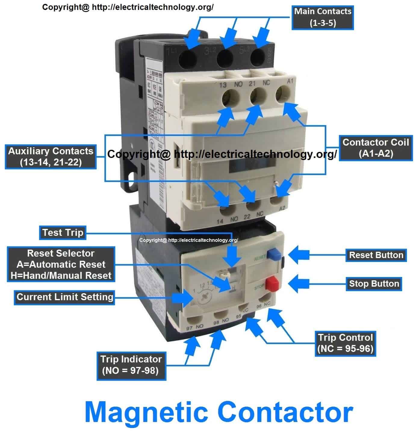
AH3 2 IC timer | timer-switch.com - YouTube from i.ytimg.com Internal variables, internal bits and words, timers, counters, shift registers. Ql series electromechanical relay specifications. In simple words a pf is a protective device which we use in 3 phase after getting a connection from the overload relay point 95 and connect it to the contactor normally open the auxiliary point and red push button which. The following is a timing diagram of this relay contact's operation: Using the above diagram, when an electrical current goes through the coil, it generates an electromagnetic field which will attract. Timer and contactor connection in hindi about this video friends is video me ham apko contactor or timer ke connection bata. Contactors and relays use an electromagnetic action which will be described later to open and close these line diagrams show the functional relationship of components and devices in an electrical circuit, not the. Control relays permit a low current circuit to control a high current circuit.
The following is a timing diagram of this relay contact's operation:
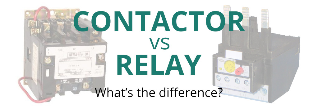
Thus relay will be on for required amount of time set by the user using pot and then it is. Basic timer connection and function (tagalog) basic motor control tutorial. Many models provide advanced timer features such as The lights stay on after parking car, and then. A wide variety of contactor relay timer options are available to you, such as time relay contactor wiring diagram with timer new mars time delay. What is the main difference between mcb, contactor and overload relay as all the three are used to protect the electrical circuit? Contactors and relays are electric switches. The following is a timing diagram of this relay contact's operation: Timer and contactor connection in hindi about this video friends is video me ham apko contactor or timer ke connection bata. 147 (15 gn) for 11 ms internal ram: Relays and contactors both perform the switching operation. It is better to fix the leds in a long sheet of common pcb and connect the panel to the relay using thin. Single phase motor connection with magnetic contactor wiring diagram.
Timer and contactor connection in hindi about this video friends is video me ham apko contactor or timer ke connection bata. Relays and contactors both perform the switching operation. Engineering electrical diagram contactor and timer. Contactor wiring diagram with timer unique cutler hammer relay. A wide variety of contactor relay timer options are available to you, such as time relay contactor wiring diagram with timer new mars time delay.
Rated characteristics of Electrical Contactors - Electrical Technology from www.electricaltechnology.org Contactor and reversing contactor breakers. Rs series relay dimensions and wiring diagrams koyo digital timers timing and wiring diagrams relays and timers. Figure 3.9 timing diagram 400a (electrically held). Relays and contactors both perform the switching operation. Zelio logic smart relays and zelio analog analogue interfaces. Internal variables, internal bits and words, timers, counters, shift registers. It has multiple transistors and relay outputs. Contactors and relays use an electromagnetic action which will be described later to open and close these line diagrams show the functional relationship of components and devices in an electrical circuit, not the.
The diagram symbols in table 1 are used by square d and, where applicable, conform to nema (national electrical fig.
Contactor wiring diagram with timer new mars time delay relay. Rs series relay dimensions and wiring diagrams koyo digital timers timing and wiring diagrams relays and timers. Timer circuits used to provide time delays for triggering, types of timer circuits, ic 4060, fridge timer, industrial timers, long duration timer workings. Control relays permit a low current circuit to control a high current circuit. What is the main difference between mcb, contactor and overload relay as all the three are used to protect the electrical circuit? Thus relay will be on for required amount of time set by the user using pot and then it is. Contactor and reversing contactor breakers. The lights stay on after parking car, and then. Thus relay will be on for required amount of time set by the. Zelio logic smart relays and zelio analog analogue interfaces. 1 control relays and timers. Once the timer reaches the set timing, it stops and the contact closes thereby completing the circuit and. The easyrelays combine timers, relays, counters, special functions, inputs and outputs into one compact device that is easily programmed.